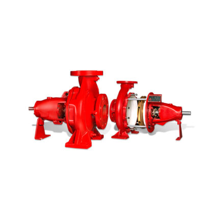
Fire Pump Controllers
Description
All Fire Pump Controllers are factory assembled, wired, and comply to all requirements of the latest edition of NFPA-20 (Centrifugal Fire Pumps) and NFPA-70 (National Electrical Code). All controllers are Y2K compliant.
Attachment
Related products
EDJ Type – Standard Pumps
| Flow (GPM) | Skid Width (mm) | Skid Height (mm) | Skid Length (mm) | Diesel Engine (HP) | Motor (HP) | Jockey (HP/GPM) | Header Pipe |
|---|---|---|---|---|---|---|---|
| 50 | 650 | 1250 | 1230 | 8 | 5.5 | 3 / 10 | 2" |
| 120 / 150 | 1220 | 1300 | 1220 | 15 | 15 | 3 / 10 | 2.5" |
| 250 / 300 | 1220 | 1420 | 1220 | 25 | 30 | 3 / 15 | 4" |
| 350 | 1550 | 1630 | 1600 | 40 | 40 | 3 / 20 | 4" |
| 500 | 1600 | 1420 | 1800 | 60 | 50 | 5.5 / 25 | 6" |
| 750 | 1700 | 1300 | 1800 | 85 | 75 | 5.5 / 35 | 6" |
| 1000 | 1700 | 1250 | 2000 | 100 | 100 |
Split Case Fire Pump
DJ Type – Standard Pumps
| Flow (GPM) | Skid Width (mm) | Skid Height (mm) | Skid Length (mm) | Diesel Engine (HP) | Jockey (HP/GPM) | Header Pipe |
|---|---|---|---|---|---|---|
| 50 | 700 | 1230 | 830 | 10 | 3 / 10 | 1.5" |
| 120 / 150 | 800 | 1280 | 1220 | 25 | 3 / 10 | 2" |
| 250 / 300 | 800 | 1420 | 1220 | 25 | 3 / 15 | 4" |
| 500 | 1000 | 1670 | 1600 | 60 | 5.5 / 25 | 6" |
| 750 | 1100 | 1760 | 1700 | 85 | 5.5 / 35 |
4 zone fire alarm control panel
Centrifugal End Suction Fire Pumps
| Model No. | Rated Capacity (GPM) | Size(SucXDis) (inches) | UL Listed Rated Net Pressure Range (PSI) | FM Approved Rated Net Pressure Range (PSI) | SETSCO & CE Pressure(PSI) | Approx Speed (RPM) | Max Working Pressure (PSI) |
|---|---|---|---|---|---|---|---|
| SFP-50-20 EM-2G | 50 | 2 ½ X 2 | 74 - 93 | 74 - 93 | 74 - 93 | 2900 | 180 |
| SFP-50-20 EM-2G | 50 | 2 ½ X 2 | 79 - 99 | 79 - 99 | 79 - 99 | 3000 | 180 |
| SFP 50-20 EM | 50 | 2 x 1 ¼ | 68 - 87 | 68 - 88 | 68 - 87 | 2900 | 230 |
| SFP 50-20 EH | 50 | 2 x 1 ¼ | 101 -129 | 102 - 129 | 101 -129 | 3500 | 230 |
| SFP 50-26 EM | 50 | 2 x 1 ¼ | 115 -140 | 115 - 133 | 115 -140 |
Matrix Network Vision Anchor
Matrix Network Vision Anchor
The large, full-color graphic display with touch screen functionality provides fire alarm system status information to single or multiple locations. Matrix Vision Annunciator can be configured to provide full display and control to replicate fire control panel functionality or to act as a simple display device for applications where access to fire alarm system control is inconvenient.
Electric Driven Skids
Features
- Driven by UL Listed Electric Motor.
- Well aligned and Coupled for Direct Operation.
- Skid Packages are Pre-Tested and Inspected thoroughly before release to customers.
- Engineered, coated, hot rolled mild steel to resist corrosion and abrasion.
- Compact skid Design with Small Foot-Print for Retrofit.
- High standard of Quality in material Construction finish and Workmanship
Gas extinguishing panel
Model Number: LF/EX
Attributes
Solid steel powder-coated cabinet
Built-in battery and internal charger
System status indicator
Charge & error indicators. Battery failure
Alarm circuits monitored for both open and short circuit
Manual trigger switch on front
2 monitored detection zones
Gas release
knockout monitored on top and bottom sides for easy installation
Communication relay
Control switch Release
timer


